ARDEP Interface
To allow more than one Power IO shield to be stacked, the shields do not directly interface with the ARDEP’s GPIOs but instead use an MCP23017T \(I^2C\) port expander with individually configurable address. The shield’s \(I^2C\) address can be configured to one of the 8 available addresses using a rotary selector that is directly connected to the MCP23017T address lines.
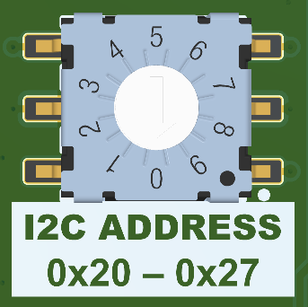
Rotary switch
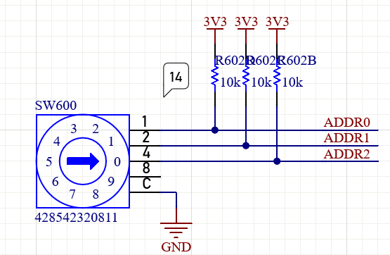
Port expander address line interface
The shield’s \(I^2C\) address is the sum of 0x20 and the number selected via the rotary switch.
Interrupts
To allow a faster response to input changes or fault conditions of the output drivers, the two interrupt lines of the MCP23017T are connected to D12 and D13 on the Arduino-like pin header, corresponding to PE5 and PE2 of the ARDEP Mainboard. The Interrupt outputs of the MCP23017T must be configured as open-drain, and the corresponding inputs on the ARDEP Mainboard need to have their internal pull-up activated.
In a stacked configuration, all port expanders can access the same two interrupt lines. Every one of them can pull the interrupt line low without interfering with the other expanders. To avoid cross-currents in case of a misconfigured interrupt output, two diodes (D201 and D204) force an open-drain behaviour and thereby guarantee that no shield can actively drive the interrupt lines high.
Pin Mapping
ARDEP pin ID |
Power expander shield pin function |
|---|---|
PE2 |
INT0 |
PE5 |
INT1 |
PA9 |
SCL |
PA8 |
SDA |