Power IO Voltage Supply
The Power IO shield has two main supply rails. It uses 3.3V as a logic supply and a high-voltage rail for the output drivers.
Logic Supply
The 3.3V logic supply is provided via the mainboard’s Arduino-like pin header and is therefore compatible with any base-boards using the same standardized pinout.
High Voltage Supply
The shield is specified to operate within a range of 12V - 48V, and a maximum total current of 10A. Exceeding this specified range is not recommended, and might lead to unexpected behaviour or physical damage to the shield. If exceeded, the first point of failure is expected to be the output driver with an 8V undervoltage lockout and a 65V absolute maximum rating.
Supply Mode Selection
The ARDEP’s Arduino-like pin header provides a direct connection to the mainboard’s high-voltage supply rail. Depending on the application, the user might want to either supply the Power IO shield from the mainboard or supply the mainboard from the IO shield. The shield’s high-voltage supply can therefore be configured to one of three available options using a 0.1” jumper header.
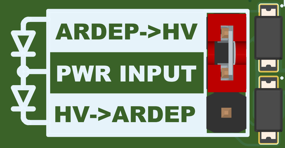
Power Configuration Header
Default: No Jumper
The high-voltage supply of the ARDEP mainboard and the Power IO Shield are decoupled and must be supplied individually. This configuration allows the user to individually select the two boards’ supply levels.
Power Via the ARDEP Mainboard
With the selection jumper in the top position, the HV outputs are powered via the ARDEP mainboard and a Schottky diode. This setting can be used if the ARDEP mainboard is connected to a high-voltage supply and the power IO outputs do not need to supply a lot of current (E.g. for testing or toggling high voltage signals)
In this configuration, the total current draw must not exceed 3A. Exceeding this limit will cause F200 to fail.
Power Via the Power IO Shield
In this configuration, the ARDEP mainboard is supplied from the Power IO Shield’s high voltage rail via a Schottky diode. Therefore, the shield has to be supplied via one of the two power connectors, and no additional supply must be connected to the ARDEP mainboard.
Power Connectors
The Power IO shield is equipped with an XT-30 connector and a 6-pin spring contact terminal. The spring contact terminal offers 3 hookup points each for GND and the positive supply. This enables the user to conveniently distribute power when using a stack multiple shields.
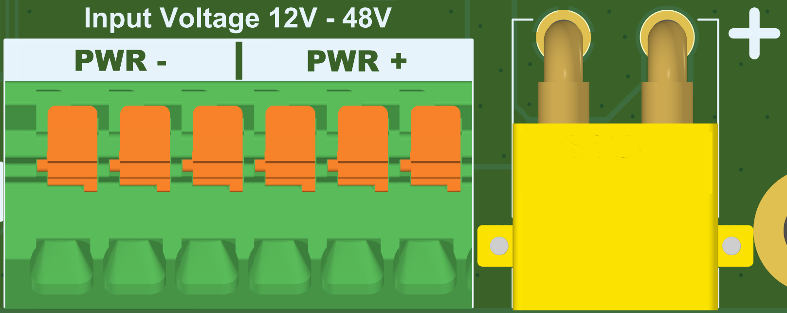
The Power IO shield’s supply connectors. Spring terminal (Left) and XT-30 connector (right)
The Spring terminals contacts are rated for 13.5 A each, and the XT30 connector is rated at 15 A. This has to be kept in mind when stacking multiple shields and routing the power via the spring contact terminals, or when stressing the shield beyond the tested current range.
Fuses
If the ARDEP Mainboard is used to supply the Power IO shield, F200, a 3A - 63V slow-blow fuse is used as a last resort to prevent uncontrolled damage to the mainboard or the shield. This fuse has to be replaced by means of soldering.
When supplied via one of the two power connectors, the shield is fused with a 10A automotive miniblade fuse. The shield is initially provided with a 0997010.WXN 10A - 58V fuse. When sourcing a replacement fuse, the user has to pay attention to the fuse’s voltage rating, as both 32V and 58V variants are available for purchase, where the first might not be safe to use in the intended application.
In case of fuse replacement, ensure that a fuse with an appropriate voltage rating is installed for the intended Application.