CAN and LIN
CAN and LIN share a single DB-9 connector in accordance with the Pinout proposed by Vector.
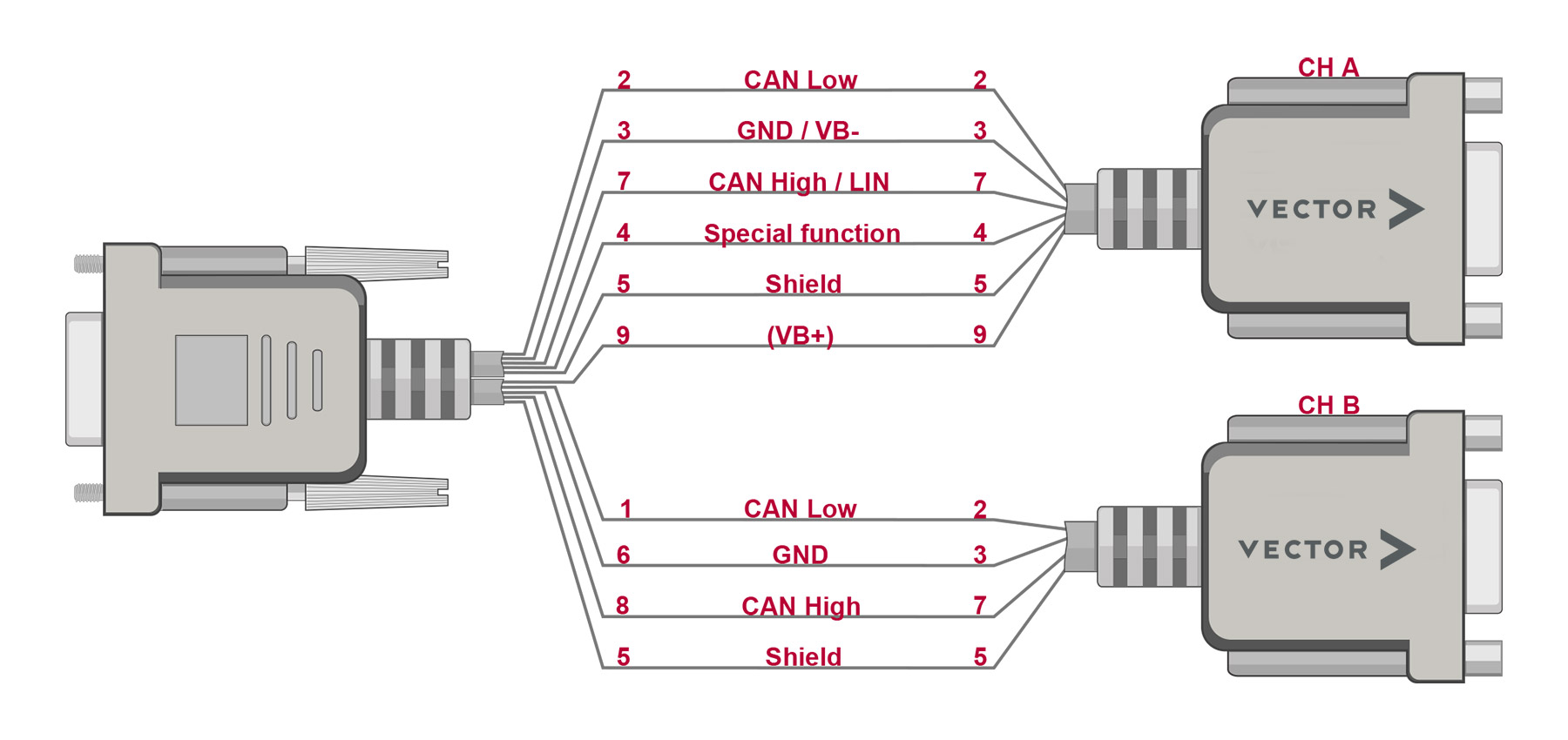
Source: Vector Website
On the ARDEP mainboard, the pinout is configured as shown below. CAN Channel B is permanently connected to the DB-9 connector. CAN Channel A and LIN are permanently connected to the spring terminal block. Using SW1, the user can choose to connect CAN-A or LIN to the DB-9 connector.
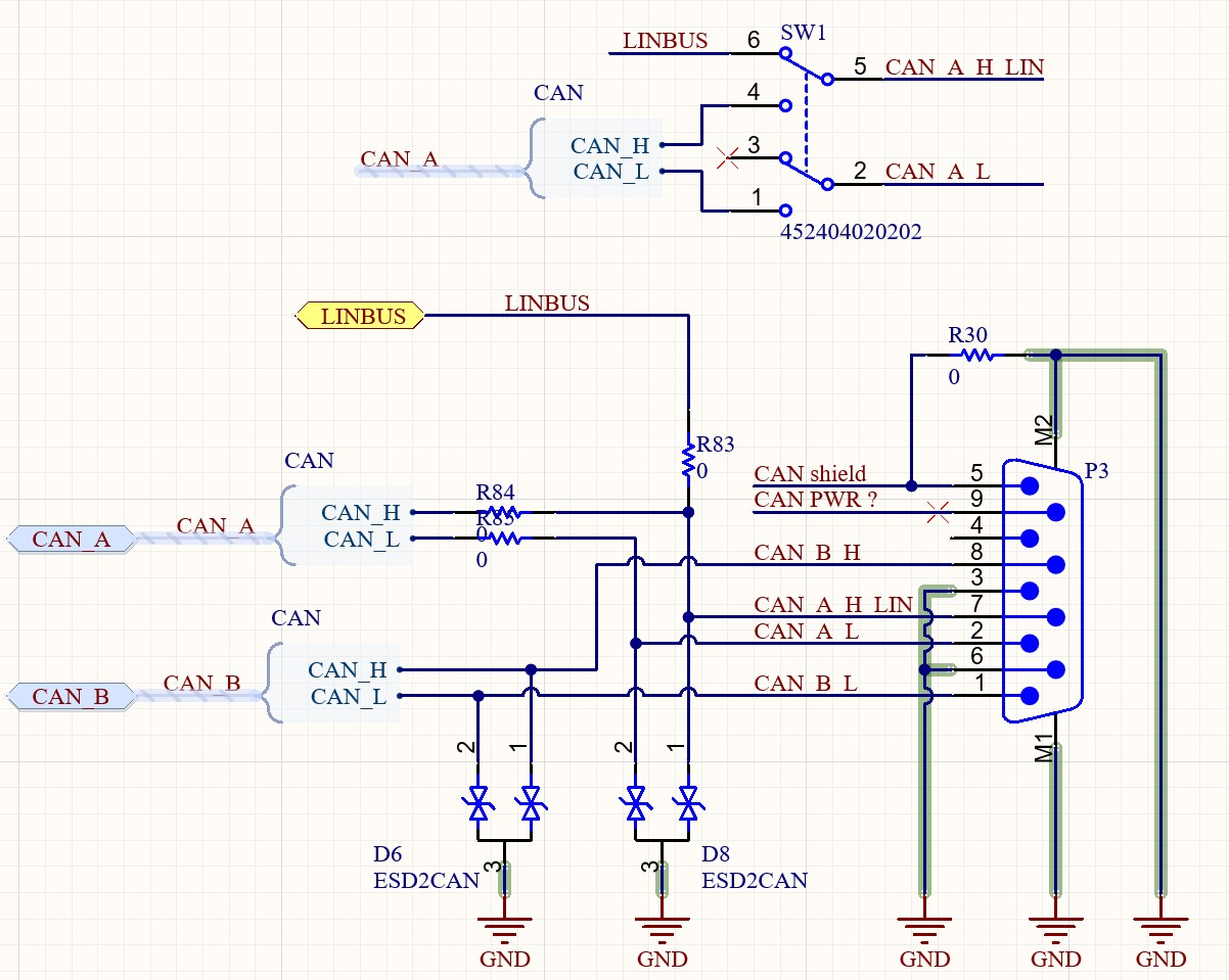
DB-9 Pinout

Spring terminal pinout
CAN
The ARDEP Mainboard comes with two CAN-FD capable CAN Transceivers. each of which, is connected to a common mode choke, ESD protection as well as a hardware configurable 120-Ohm termination.
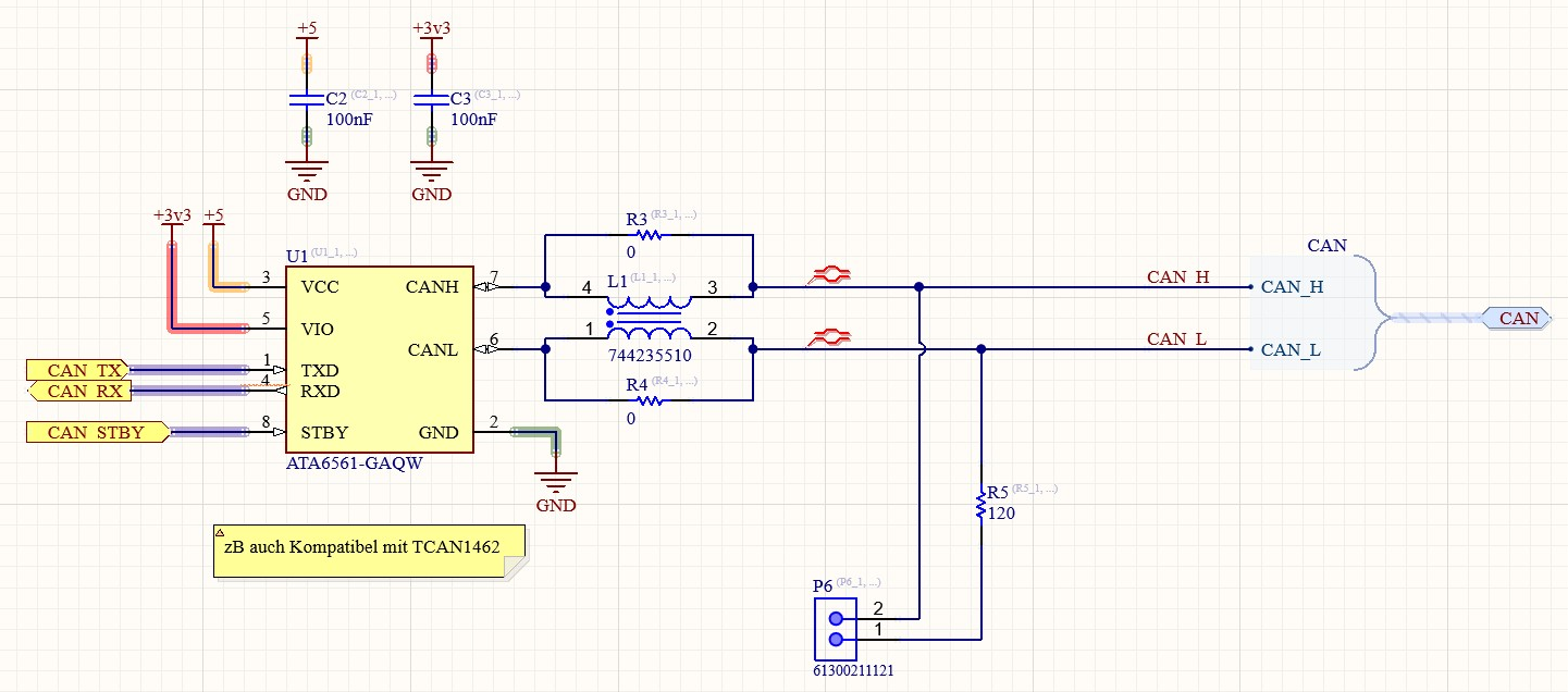
CAN Interface rev. 0.2
In rev 0.1 the Termination was implemented to be software-configurable. This feature has been removed starting from rev 0.2 due to cost and practicality reasons.
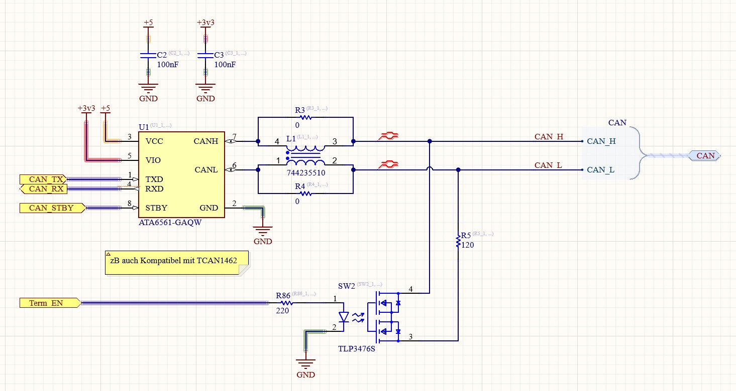
CAN Interface rev. 0.1
Pin-mapping
CAN A
CAN A is directly connected to the spring contact terminal and can be connected to the DB-9 connector with the help of SW1. lToggling SW1 will disconnect LIN from Pin7 and connect CANA to pin 7 and 2
Description |
STM32 Pin |
Comment |
|---|---|---|
CAN RX |
PD0 |
|
CAN TX |
PD1 |
|
CAN STBY |
PD2 |
|
Term_EN |
PD3 |
Only in rev 0.1 |
CAN B
CAN B is permanently connected to the CAN B channel of the DB-9 connector in accordance with the Vector pinout.
Description |
STM32 Pin |
Comment |
|---|---|---|
CAN RX |
PB5 |
|
CAN TX |
PB6 |
|
CAN STBY |
PB7 |
|
Term_EN |
PB4 |
Only in rev 0.1 |
LIN
LIN is permanently connected to the spring contact terminal and can be connected to the DB-9 connector with the help of SW1. Toggling SW1 will disconnect CAN-A from Pin 7 & 2 and instead connect LIN to Pin 7.
The User can select to Supply the LIN driver from the mainboard internal 5 V supply, or an external Supply connected to the spring contact terminal. The LIN supply is specified for up to 24 V and is additionally connected to one of the 0.1” Header connectors.
Using a solid-state Relay The LIN Interface can be software-configured for master- or slave mode.
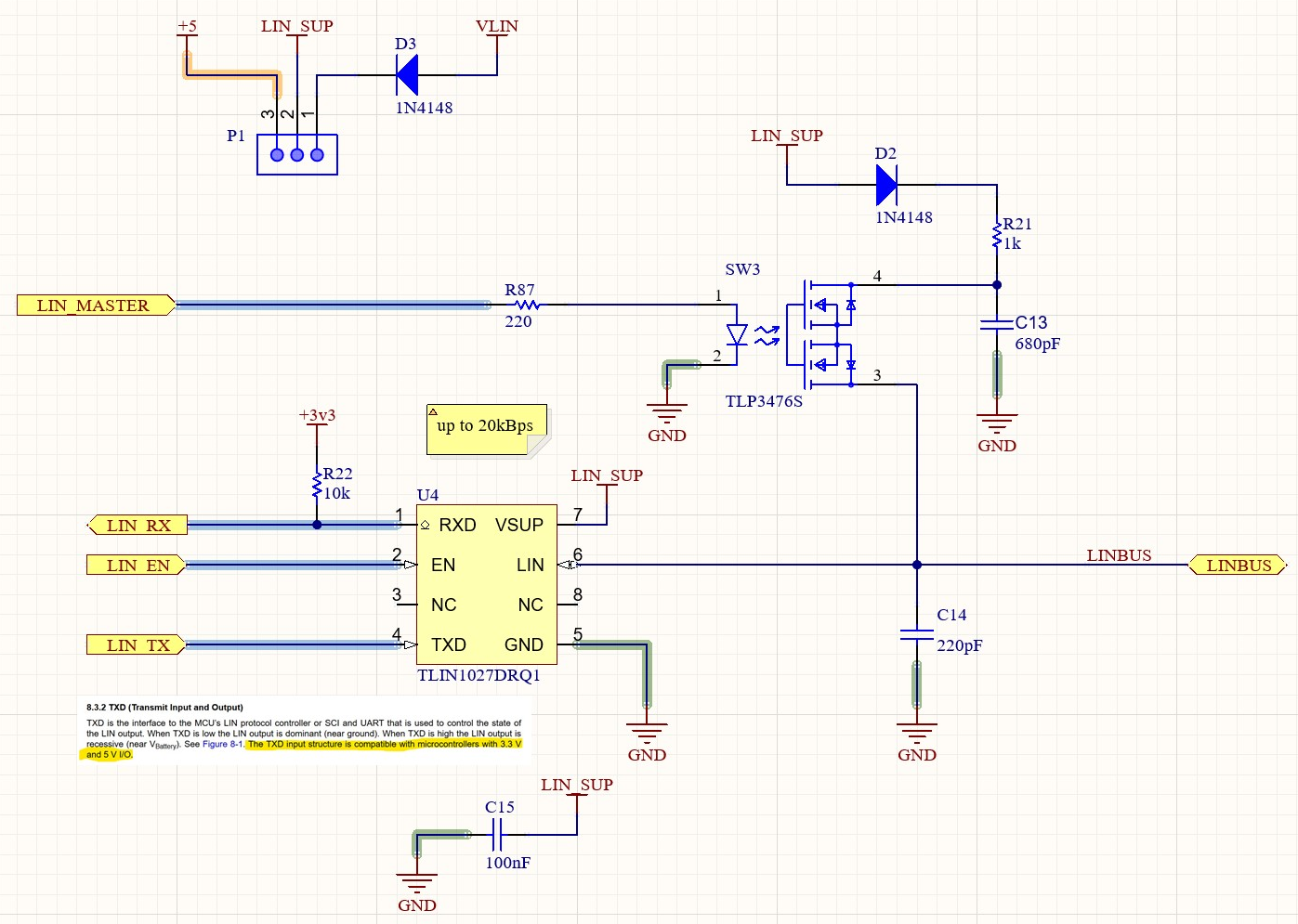
ARDEP LIN INterface
Pin-mapping
Description |
STM32-Pin |
|---|---|
LIN RX |
PE1 |
LIN TX |
PE0 |
LIN Enable |
PD7 |
LIN Master |
PB9 |