Gearshift
Starting with rev0.2 the mainboard comes with a “Gearshift“ config header. It allows the user to select different software configurations via a hardware jumper.
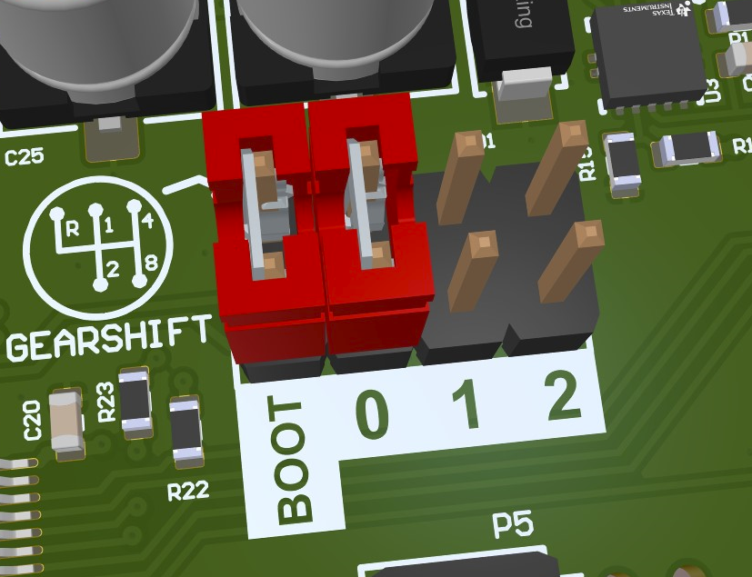
Gear Shift Header
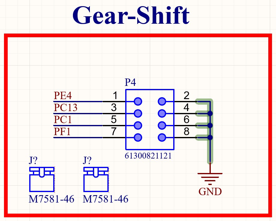
Circuit Diagram of the Gear Shift Header
The µC pins have to be configured with an internal pullup. Placing a jumper will then pull the corresponding pin low. Using purely software-defined pullups is possible because the state will only be evaluated after booting. Therefore an undefined state, before initializing the IOs can be tolerated.
Pin-mapping
µC Pin |
Position |
|---|---|
PE4 |
Boot |
PC13 |
0 |
PC1 |
1 |
PF1 |
2 |
Software Usage
The gearshift position can be read in software to dynamically configure various parameters. The three position pins (0, 1, 2) provide 8 possible configurations (0-7).
An example for reading the gearshift position is located in the Gearshift Sample.
Dynamic Address Configuration
The Gearshift Address Providers library uses the gearshift position to automatically configure CAN addresses for UDS and logging services. This allows multiple ARDEP boards on the same CAN bus to use unique addresses without requiring different firmware builds.