On-Board Debugger (OBD)
Note
The on-board debugger is available on ARDEP board revision 2.0.0 and later.
Starting from ARDEP rev2.0.0, an on-board debugger was added to the main PCB. It can be interfaced via the Debugger USB port, as indicated in the pinout overview.
The Debugger was designed to be compatible with the Blackmagic probe firmware and was implemented as depicted in the schematic below.
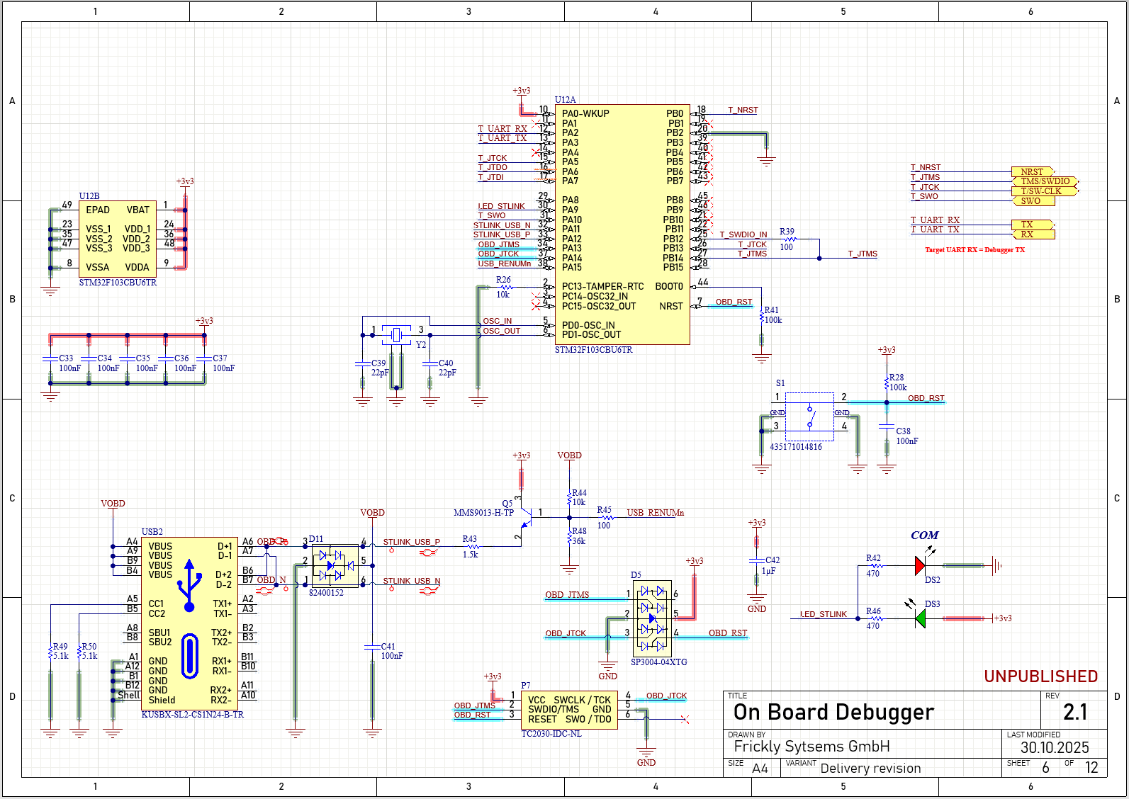
Schematic diagram overview of the on board debugger as implemented on the ARDEP mainboard
ARDEP Interface
The on-board debugger is connected to the ARDEP’s main µC as illustrated below. The Debug RX/TX Lines are connected via 1 kΩ resistors to the existing UART-A interface on the PCB. The resistors ensure that an external device connected to the same UART Interface always has priority, and TX state interference will not cause a short circuit.
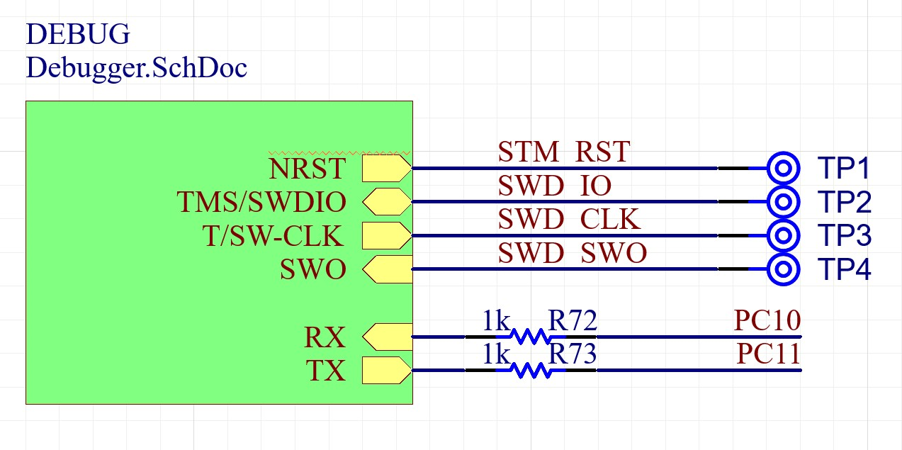
Debugger connection to the ARDEP main µC
USB Power Supply
The 5 V net of the Debug USB is ideal-diode multiplexed with the ARDEP’s main USB port; therefore, either of the two can be used to supply the mainboard with 5 V during operation.